Free-Body Diagram on an Inclined Plane Generator
Free online Free-Body Diagram on an Inclined Plane generator: get a fully labeled figure in about 90 seconds. The AI plans the must-have label list first, then renders a clean textbook-style diagram — every label editable afterwards, ready for papers, assignments and slides.
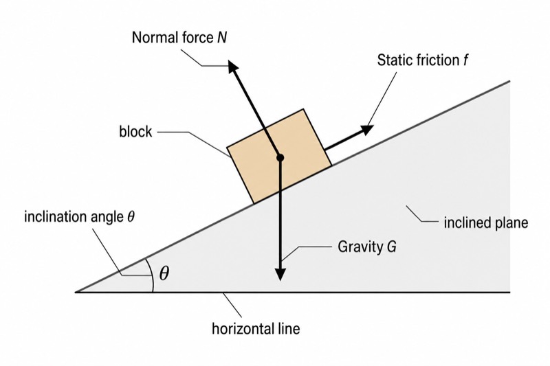
Labels included in this diagram
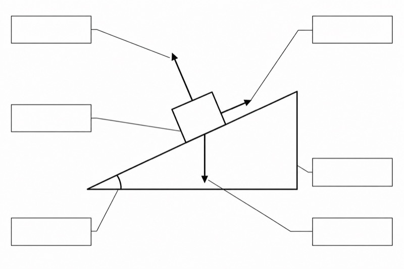
- block
- inclined plane
- horizontal line
- Gravity G
- Normal force N
- Static friction f
- inclination angle θ
✓ Accurate labels ✓ Edit text after generation ✓ PNG for papers, posters & slides
 OUTPUT · 16:9 · PNG
What this diagram shows
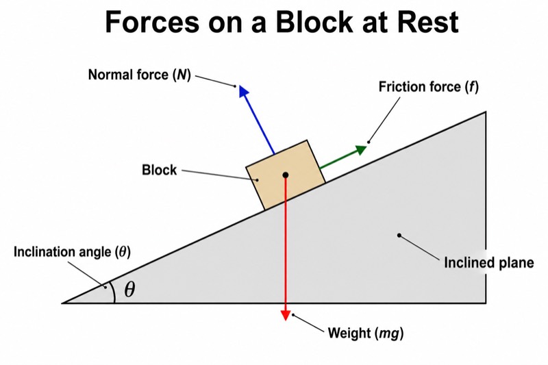
This diagram represents a block at rest on an inclined plane with inclination angle θ measured from the horizontal line. Three forces act on the isolated block: gravity G, the normal force N, and static friction f. Gravity points vertically downward toward Earth, regardless of the plane’s orientation. The normal force is perpendicular to and away from the inclined surface. Because the block would otherwise tend to slide down the plane, static friction acts parallel to the surface and points up the slope. The diagram provides the basis for applying Newton’s first law and resolving forces along axes parallel and perpendicular to the plane.
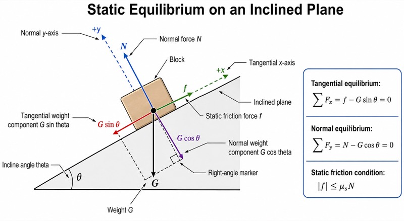
Choose the x-axis parallel to the inclined plane and the y-axis perpendicular to it. Gravity G can then be resolved into G sin θ down the slope and G cos θ into the plane. Since the block is at rest, the net force along each axis is zero. Perpendicular to the plane, N = G cos θ. Along the plane, static friction balances the downslope component, so f = G sin θ, provided that the required friction does not exceed its maximum value, f ≤ μsN. The angle between gravity and the inward normal direction is θ, which explains why the gravitational components contain sin θ and cos θ.
What a correct diagram must include
- Block: Represent the object as a simple box or point and draw only the external forces acting on it.
- Inclined plane: Draw a straight sloping surface beneath the block so that parallel and perpendicular directions are visually clear.
- Horizontal line and inclination angle θ: Add a horizontal reference line and mark θ between it and the inclined plane.
- Gravity G: Draw an arrow vertically downward from the block’s center; do not tilt it to match the plane.
- Normal force N: Draw an arrow perpendicular to the inclined plane and pointing away from the contact surface.
- Static friction f: Draw an arrow parallel to the plane and opposite the block’s possible motion; for a block tending to slide down, f points uphill.
- Force components: If components are required, label G sin θ parallel to the plane and G cos θ perpendicular into the plane, preferably in a separate resolution diagram.
- Equilibrium condition: Indicate that the stationary block satisfies ΣFparallel = 0 and ΣFperpendicular = 0.
Common mistakes
- Drawing gravity perpendicular to the inclined plane instead of vertically downward.
- Drawing the normal force vertically upward rather than perpendicular to the contact surface.
- Assuming static friction always equals μsN; static friction adjusts to the required value and only satisfies f ≤ μsN.
- Choosing the friction direction from the slope alone instead of opposing the actual or impending relative motion.
- Including both gravity G and its components G sin θ and G cos θ as separate forces in the same force sum, which double-counts gravity.
Teaching tips
Use the diagram after introducing Newton’s laws and before solving equilibrium problems on inclined planes. Ask students first to isolate the block, identify all contact and non-contact forces, and predict the direction in which it would move without friction. Then have them justify each arrow’s direction and resolve gravity using axes parallel and perpendicular to the plane. Connect the diagram to the key results N = G cos θ and f = G sin θ for equilibrium, while emphasizing the limiting condition G sin θ ≤ μsG cos θ. This prepares students for questions about impending motion, coefficient of static friction, and critical angle.
FAQ about this diagram
Why does static friction point up the inclined plane?
Gravity has a component G sin θ directed down the plane, so the block tends to slide downhill. Static friction opposes this impending relative motion and therefore points uphill.
Is static friction always equal to μsN?
No. Static friction adjusts from zero up to its maximum value μsN. For this stationary block, f = G sin θ only when that required value is no greater than μsN.
Why are axes usually chosen parallel and perpendicular to the plane?
These axes align with the directions of static friction and the normal force, reducing the number of force components. Only gravity needs to be resolved, giving G sin θ along the plane and G cos θ perpendicular to it.