Detailed Free Body Diagram (University Level)
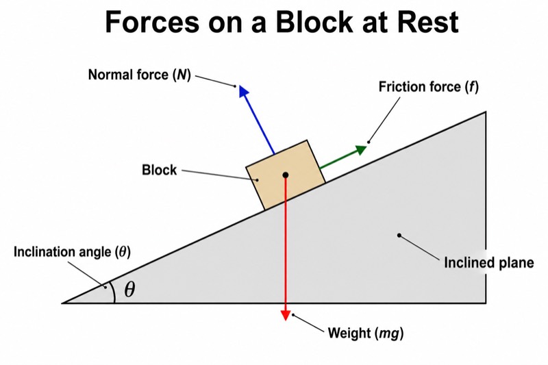
Detailed Free Body Diagram (University Level) — an alternative version of the Free-Body Diagram on an Inclined Plane, generated by AI and fully editable. Download the PNG for quizzes, homework or slides.
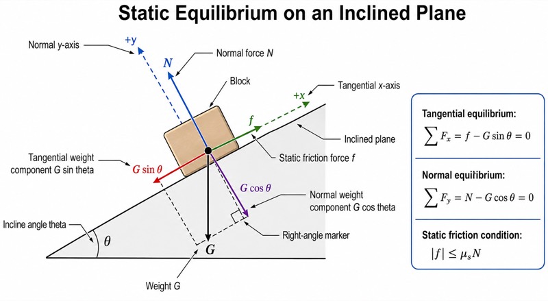
Labels included in this diagram
- Block
- Inclined plane
- Weight G
- Normal force N
- Static friction force f
- Tangential weight component G sin theta
- Normal weight component G cos theta
- Incline angle theta
- Tangential x-axis
- Normal y-axis
- Right-angle marker
- Tangential equilibrium: sum F_x = f - G sin theta = 0
- Normal equilibrium: sum F_y = N - G cos theta = 0
- Static friction condition: |f| <= mu_s N
✓ Accurate labels ✓ Edit text after generation ✓ PNG for papers, posters & slides
 OUTPUT · 16:9 · PNG
What this diagram shows
This detailed free body diagram (university level) represents a stationary block on an inclined plane. Unlike the standard main diagram, which shows only weight G, normal force N, static friction f, and angle θ, this version resolves G into the orthogonal components G sin θ and G cos θ. It also includes dashed tangential and normal axes, arrow directions, a right-angle marker, the contact point, the plane surface, and equilibrium equations. These added structures make the diagram suitable for formal derivations rather than basic force recognition.
Read the diagram by choosing the dashed x-axis parallel to the plane and the y-axis perpendicular to it, then project every force onto those axes. For equilibrium, use ΣF∥ = 0 and ΣF⊥ = 0, giving f = G sin θ and N = G cos θ when no other forces act. Check static friction with f ≤ μsN; impending slip occurs when f = μsN, so tan θ = μs. Use this expanded version when the standard main figure does not provide enough information for component analysis or friction-limit reasoning.
Teaching tips
- In-class quizzes: ask students to identify and label at least twelve structures, including the block, inclined surface, contact point, G, N, f, G sin θ, G cos θ, θ, both dashed axes, and the right-angle marker before writing the two equilibrium equations.
- Homework derivations: provide the figure without the equations and require students to derive N = G cos θ, f = G sin θ, and the no-slip condition tan θ ≤ μs. This version is preferable to the standard diagram because the projection geometry is explicitly visible.
- Lecture slides: reveal the force vectors first, then the orthogonal decomposition, and finally the equilibrium and friction relations. The staged reading helps distinguish a real force such as G from calculated components such as G sin θ and G cos θ.
- Review outlines and printed handouts: place the diagram beside a sign-convention checklist so students can verify axis orientation, component signs, friction direction, and the distinction between f ≤ μsN and the limiting case f = μsN.
- Reports, theses, and paper illustrations: use this rigorous layout when a simplified main figure would leave the coordinate basis or equilibrium assumptions ambiguous. Define θ and μs in the caption and state that the block is static, the contact is dry, and the plane is treated as rigid.
FAQ about this diagram
Why is static friction not always written as f = μsN?
Static friction adjusts to the value required for equilibrium, up to the maximum μsN. Therefore, f = G sin θ for the stationary block, while f = μsN applies only at impending slip.
Why use this university-level version instead of the standard inclined-plane diagram?
The standard version is sufficient for recognizing the main forces, but it does not fully document projections, coordinate choices, or limiting-friction conditions. This detailed version is needed for derivations, sign checks, quantitative problem solving, and publication-quality technical explanations.