Series Circuit Diagram Generator
Free online Series Circuit Diagram generator: get a fully labeled figure in about 90 seconds. The AI plans the must-have label list first, then renders a clean textbook-style diagram — every label editable afterwards, ready for papers, assignments and slides.
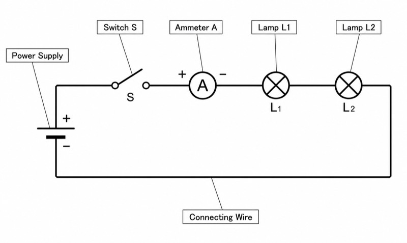
Labels included in this diagram
- Power Supply
- Switch S
- Lamp L1
- Lamp L2
- Ammeter A
- Connecting Wire
✓ Accurate labels ✓ Edit text after generation ✓ PNG for papers, posters & slides
 OUTPUT · 16:9 · PNG
What this diagram shows
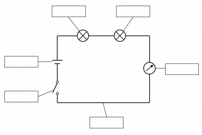
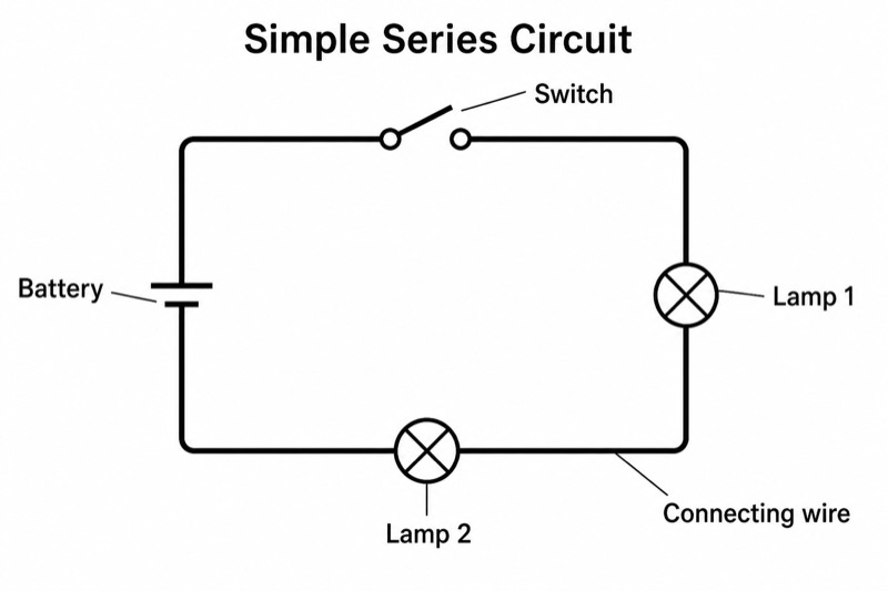
This series circuit diagram represents a complete electrical circuit containing a power supply, Switch S, Lamp L1, Lamp L2, Ammeter A, and connecting wires. All components are arranged in a single closed loop, so electric current has only one path through the circuit. When Switch S is closed, conventional current flows from the positive terminal of the power supply, through each component in sequence, and back to the negative terminal. Because the lamps are connected in series, the same current passes through L1 and L2.
The power supply provides the potential difference that drives charge around the circuit. Switch S controls whether the conducting path is complete: an open switch stops the current, while a closed switch allows it to flow. Ammeter A is connected in series so that the entire circuit current passes through it. Lamp L1 and Lamp L2 share the supply voltage, and their individual potential differences add to the total supply voltage. If either lamp is removed or fails, the single path is broken and both lamps go out.
What a correct diagram must include
- Power supply: Draw the correct standard cell or battery symbol and clearly distinguish its positive and negative terminals.
- Switch S: Place a standard switch symbol in the single loop and show clearly whether the switch is open or closed.
- Lamp L1: Use the standard lamp symbol and label it L1 so it can be identified in questions and measurements.
- Lamp L2: Draw a second standard lamp symbol in the same current path and label it L2.
- Ammeter A: Use a circle containing the letter A and connect it in series, never across a lamp or the power supply.
- Connecting wire: Use straight, continuous lines to join all components without creating branches or unintended gaps.
- Single closed path: Check that current can pass through S, A, L1, and L2 in sequence when the switch is closed.
- Standard symbols and junctions: Use recognized national-standard schematic symbols and mark connected wire junctions clearly when necessary.
Common mistakes
- Drawing L1 and L2 on separate branches, which makes the circuit parallel rather than series.
- Connecting Ammeter A across a lamp or the power supply; an ammeter must be placed in the main current path.
- Leaving an unintended gap in a wire while showing Switch S as closed, so the circuit is not actually complete.
- Using realistic pictures of bulbs and batteries instead of standard circuit symbols.
- Assuming current is used up by L1, even though the current is the same at every point in an ideal series circuit.
Teaching tips
Use the diagram after students have learned standard circuit symbols and before practical circuit construction. Ask them to trace the conventional current, identify the single path, predict what happens when Switch S is opened, and explain why both lamps go out if L1 fails. Students can also predict ammeter readings at different positions and compare the voltage across each lamp. The diagram supports common assessment points: recognizing series connections, placing an ammeter correctly, distinguishing current from voltage, and diagnosing an incomplete circuit.
FAQ about this diagram
Why is the current the same through Lamp L1 and Lamp L2?
A series circuit has only one path for charge flow, so charge cannot split between branches. Therefore, the current through L1, L2, and Ammeter A is the same.
What happens when Switch S is opened?
Opening Switch S breaks the conducting path, so no current flows anywhere in the circuit. Both L1 and L2 go out, and Ammeter A reads zero.
How do two series lamps affect resistance and brightness?
Their resistances add, so the total circuit resistance is greater than that of either lamp alone. For identical lamps and a fixed power supply, the current is reduced and the supply voltage is shared, so each lamp is usually dimmer than a single lamp connected to the same supply.