Ray Diagram for Image Formation by a Convex Lens Generator
Free online Ray Diagram for Image Formation by a Convex Lens generator: get a fully labeled figure in about 90 seconds. The AI plans the must-have label list first, then renders a clean textbook-style diagram — every label editable afterwards, ready for papers, assignments and slides.
Labels included in this diagram
- Convex lens
- Principal axis
- Optical center O
- F
- 2F
- Object
- Real image
- Ray parallel to principal axis
- Refracted ray through F
- Ray through optical center
- Incident ray through F
- Refracted ray parallel to principal axis
✓ Accurate labels ✓ Edit text after generation ✓ PNG for papers, posters & slides
 OUTPUT · 16:9 · PNG
What this diagram shows
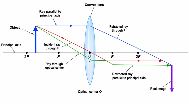
This ray diagram shows image formation by a convex lens when the object is placed between one focal length and two focal lengths, marked F and 2F. Three principal rays are drawn from the top of the object. A ray parallel to the principal axis refracts through the far focal point. A ray passing through the optical center O continues in a straight line. A ray directed through the near focal point emerges parallel to the principal axis. The refracted rays meet beyond 2F on the opposite side of the lens, forming a real, inverted, and enlarged image.
The principal axis provides the reference line for placing the object, lens, focal points, and image. The optical center O lies where the axis crosses the lens, while F and 2F must be marked symmetrically on both sides. Because the object is between F and 2F, the refracted rays actually converge beyond 2F. Their intersection locates the top of the image, and the principal axis locates its base. The image is inverted because the rays cross after refraction, enlarged because its height exceeds the object's height, and real because the outgoing light rays physically meet and can form an image on a screen.
What a correct diagram must include
- Principal axis — draw a straight horizontal reference line through the center of the lens so all distances and ray directions can be compared correctly.
- Convex lens and optical center O — draw the lens centered on the principal axis and label O at their intersection.
- Focal points F — mark equal focal distances on both sides of the lens because a convex lens has a principal focus on each side.
- Points 2F — place each 2F point at twice the focal distance from O, symmetrically on the two sides.
- Object between F and 2F — draw an upright arrow on one side of the lens with its base on the principal axis.
- Three principal rays — include the parallel ray refracted through the far F, the ray through O that remains straight, and the ray through the near F that emerges parallel.
- Image beyond 2F — place an inverted arrow where the refracted rays intersect on the opposite side, and make it taller than the object.
- Image description — label the image as real, inverted, and enlarged to connect the construction with the imaging rule.
Common mistakes
- Placing the object at F, at 2F, or outside 2F instead of clearly between F and 2F, which changes the image position and size.
- Drawing the parallel incident ray through the near focal point rather than refracting it through the focal point on the opposite side.
- Bending the ray that passes through O, even though the standard thin-lens model shows it continuing without a change in direction.
- Drawing the third ray through the far focal point before it reaches the lens; it must be directed through the near focal point and then emerge parallel to the principal axis.
- Marking the image between F and 2F or drawing it upright; for this object position, the image must be beyond 2F, inverted, enlarged, and real.
Teaching tips
Use the diagram after students have learned refraction and the meanings of focal length and optical center. First hide the completed image and ask students to predict where each principal ray travels after passing through the lens. Then let them locate the image from the intersection of any two refracted rays and use the third ray as a check. Questions should connect object position with image position, orientation, size, and type. This directly prepares students for ray-construction questions, image-property tables, and experiments using a screen.
FAQ about this diagram
Why are three principal rays drawn if only two are needed to locate the image?
Any two correctly drawn principal rays determine the image position. The third ray confirms the construction and helps reveal drawing errors.
Why is the image real and inverted when the object is between F and 2F?
The refracted rays physically converge on the opposite side of the lens, so the image is real and can be projected onto a screen. The rays cross before forming the image, placing the image below the principal axis and making it inverted.
Where should the image be formed, and how large should it be?
The image forms beyond 2F on the side opposite the object. It is enlarged, so the image arrow should be taller than the object arrow, although an exact scale is required only when distances are measured.