Reflection and Refraction of Light Generator
Free online Reflection and Refraction of Light generator: get a fully labeled figure in about 90 seconds. The AI plans the must-have label list first, then renders a clean textbook-style diagram — every label editable afterwards, ready for papers, assignments and slides.
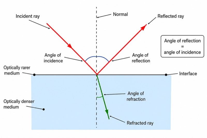
Labels included in this diagram
- Incident ray
- Reflected ray
- Refracted ray
- Normal
- Interface
- Angle of incidence
- Angle of reflection
- Angle of refraction
- Angle of reflection = angle of incidence
- Optically rarer medium
- Optically denser medium
✓ Accurate labels ✓ Edit text after generation ✓ PNG for papers, posters & slides
 OUTPUT · 16:9 · PNG
What this diagram shows
This diagram shows what happens when an incident ray reaches the interface between two transparent media. Part of the light returns to the first medium as the reflected ray, while the rest enters the second medium as the refracted ray. A normal is drawn perpendicular to the interface at the point of incidence. The angle of incidence, angle of reflection, and angle of refraction are all measured between their rays and the normal. The diagram demonstrates the law of reflection: the angle of reflection equals the angle of incidence.
The incident ray, reflected ray, refracted ray, and normal meet at the same point of incidence. The reflected ray stays in the original medium and is symmetric to the incident ray about the normal. When light travels from an optically rarer medium into an optically denser medium, it slows down and bends toward the normal, so the angle of refraction is smaller than the angle of incidence. When it travels from an optically denser medium into an optically rarer medium, it speeds up and bends away from the normal.
What a correct diagram must include
- Interface: Draw a clear straight boundary separating two transparent media so the change in the direction of light can be identified.
- Optical media: Label the two sides as an optically rarer medium and an optically denser medium; optical density refers to light speed, not simply mass density.
- Point of incidence: Mark the exact point where the incident ray meets the interface because every ray and the normal must meet there.
- Normal: Draw a dashed line perpendicular to the interface at the point of incidence and show the right angle clearly.
- Three rays: Label the incident ray, reflected ray, and refracted ray, and add arrowheads to indicate the direction in which light travels.
- Three angles: Mark the angle of incidence, angle of reflection, and angle of refraction between each ray and the normal, never between a ray and the interface.
- Law of reflection: State that the angle of reflection equals the angle of incidence and draw the reflected ray symmetrically about the normal.
- Refraction direction: Show the ray bending toward the normal when entering an optically denser medium and away from the normal when entering an optically rarer medium.
Common mistakes
- Measuring the angles from the interface instead of from the normal, which gives incorrect angle values.
- Drawing the normal at an oblique angle; it must be exactly perpendicular to the interface at the point of incidence.
- Giving the reflected ray a different angle from the incident ray, contrary to the law of reflection.
- Bending light away from the normal when it enters an optically denser medium, or toward the normal when it enters an optically rarer medium.
- Confusing the reflected ray with the refracted ray: the reflected ray remains in the first medium, while the refracted ray crosses the interface.
Teaching tips
Use the diagram after students have observed reflection in a mirror and refraction through glass or water. First hide the ray labels and ask students to identify each ray, the interface, the normal, and the point of incidence. Then ask where each angle must be measured and have students predict the reflected and refracted directions. Connect their answers to the law of reflection and the rule for bending toward or away from the normal. The diagram supports exam questions on completing ray paths, labeling angles, comparing angle sizes, and identifying optical density.
FAQ about this diagram
Why are the angles measured from the normal rather than from the interface?
The normal provides a fixed perpendicular reference at the point of incidence. The laws of reflection and refraction define all relevant angles between a light ray and this normal.
Why does light bend when it crosses the interface?
Light changes speed when it enters a medium with a different optical density. This speed change alters its direction unless the ray travels along the normal.
Does light always produce both a reflected ray and a refracted ray?
At many transparent interfaces, some light is reflected and some is refracted. However, under total internal reflection, light traveling from an optically denser medium may be completely reflected when the angle of incidence exceeds the critical angle.