Detailed Circuit Diagram (University Level)
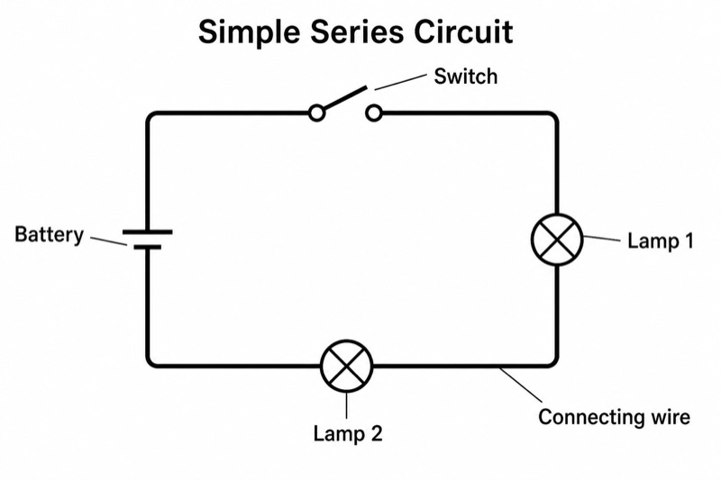
Detailed Circuit Diagram (University Level) — an alternative version of the Series Circuit Diagram, generated by AI and fully editable. Download the PNG for quizzes, homework or slides.
Labels included in this diagram
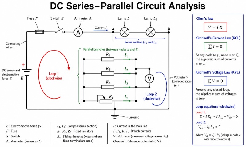
- DC source and electromotive force E
- Switch S
- Fuse F
- Connecting wires
- Fixed resistors R1, R2, R3
- Sliding rheostat Rv
- Lamp L1
- Lamp L2
- Ammeter A and voltmeter V
- Ground
- Series section and parallel branches
- Nodes a and b; loops 1 and 2
- Currents I, I1, I2
- Ohm's law and Kirchhoff equations: V=IR; sum I=0; sum V=0
✓ Accurate labels ✓ Edit text after generation ✓ PNG for papers, posters & slides
 OUTPUT · 16:9 · PNG
What this diagram shows
This detailed circuit diagram (university level) expands the standard two-lamp series diagram into a mixed series-parallel network with more than twelve labeled structures. It includes a DC source with electromotive force E, a switch, fuse, fixed resistors R1, R2, and R3, a sliding rheostat, a lamp, an ammeter, a voltmeter, connecting wires, nodes, loops, and a ground reference. Unlike the standard main diagram, which isolates the basic idea of one current path, this version shows realistic measurement connections, branch currents, and circuit protection using standardized GB/IEC-compatible symbols.
Read the diagram first by tracing conventional current from the positive source terminal through the fuse, switch, and series section. At each labeled node, follow the arrows showing how the total current divides among parallel branches and recombines. The ammeter is connected in series, while the voltmeter is connected in parallel across the selected component. Use the loop labels and node labels to connect the drawing with Ohm’s law, V = IR, Kirchhoff’s current law, and Kirchhoff’s voltage law. This version is preferable when the standard diagram lacks enough structure for quantitative analysis, laboratory planning, or formal technical explanation.
Teaching tips
- In-class quizzes: remove selected current arrows, node names, or meter labels and ask students to restore them, identify series and parallel sections, and explain why the ammeter and voltmeter use different connections.
- Homework: assign numerical values to E, R1, R2, R3, the lamp resistance, and the rheostat setting; students can calculate equivalent resistance, branch currents, voltage drops, fuse current, and source power.
- Lecture slides and review outlines: reveal the network in stages—from the standard two-lamp series circuit to the full mixed circuit—to show exactly why this university-level version is needed for node, branch, and loop analysis.
- Laboratory handouts: use the labeled switch, fuse, meters, rheostat, and ground reference as a wiring plan, then require students to compare measured values with predictions from Ohm’s law and Kirchhoff’s equations.
- Paper figures and printed notes: use the rigorous symbol set, non-crossing leads, formal component names, and equation panel when a simple main diagram would be too schematic for a methods section or advanced derivation.
FAQ about this diagram
How is this university-level diagram different from the standard series-circuit diagram?
The standard diagram emphasizes a single current path through two lamps. This variant adds a mixed series-parallel topology, source electromotive force, protection, adjustable resistance, measuring instruments, nodes, branch-current directions, loop labels, and governing equations, making it suitable for quantitative circuit analysis.
Why use this detailed version instead of adding more labels to the standard main diagram?
Additional labels alone cannot represent current division, parallel voltage relationships, instrument loading positions, or independent Kirchhoff equations. This version is needed when students must move beyond recognizing components and instead formulate node equations, loop equations, measurement procedures, and experimentally testable predictions.