Water Electrolysis Experimental Setup Generator
Free online Water Electrolysis Experimental Setup generator: get a fully labeled figure in about 90 seconds. The AI plans the must-have label list first, then renders a clean textbook-style diagram — every label editable afterwards, ready for papers, assignments and slides.
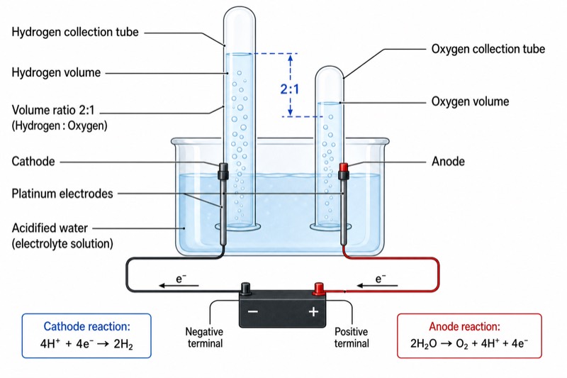
Labels included in this diagram
- Positive terminal
- Negative terminal
- Anode
- Cathode
- Platinum electrodes
- Acidified water (electrolyte solution)
- Hydrogen collection tube
- Oxygen collection tube
- Hydrogen volume
- Oxygen volume
- Volume ratio 2:1
- Anode reaction: 2H2O→O2+4H+ +4e−
- Cathode reaction: 4H+ +4e−→2H2
✓ Accurate labels ✓ Edit text after generation ✓ PNG for papers, posters & slides
 OUTPUT · 16:9 · PNG
What this diagram shows
The diagram shows the electrolysis of water using a direct-current power supply, inert electrodes, an electrolyte solution, and two graduated gas-collection tubes. The positive terminal is connected to the anode, where oxygen is produced, while the negative terminal is connected to the cathode, where hydrogen is produced. For acidified water, the cathode half-equation is 2H+ + 2e− → H2, and the anode half-equation is 2H2O → O2 + 4H+ + 4e−. The overall reaction is 2H2O → 2H2 + O2. The collected hydrogen volume is therefore twice the oxygen volume under the same temperature and pressure.
The power supply drives electrons through the external circuit and causes ions in the electrolyte solution to migrate toward the electrodes. At the cathode, reduction occurs because hydrogen ions or water molecules gain electrons to form hydrogen gas. At the anode, oxidation occurs because water or hydroxide ions lose electrons to form oxygen gas. Each inverted collection tube must be positioned directly above one electrode so that the gases remain separate. The stoichiometric coefficients in the overall equation explain the volume relationship: two moles of hydrogen are formed for every mole of oxygen. Consequently, the hydrogen and oxygen columns should be drawn with a 2:1 volume ratio.
What a correct diagram must include
- DC power supply with positive and negative terminals: mark the polarity clearly because electrode identity is determined by the terminal connection.
- Anode connected to the positive terminal: label it as the site of oxidation and oxygen production.
- Cathode connected to the negative terminal: label it as the site of reduction and hydrogen production.
- Two inert electrodes: draw platinum or another suitable inert material immersed in the solution so that the electrodes do not introduce additional products.
- Electrolyte solution: label acidified water, such as water containing dilute sulfuric acid, because pure water conducts electricity too poorly for a clear demonstration.
- Two inverted graduated gas-collection tubes: place one directly over each electrode and begin with the tubes completely filled with solution.
- Gas labels and volumes: show H2 above the cathode and O2 above the anode, with the hydrogen volume twice the oxygen volume.
- Half-equations and overall equation: include 2H+ + 2e− → H2, 2H2O → O2 + 4H+ + 4e−, and 2H2O → 2H2 + O2.
Common mistakes
- Reversing the electrode labels: in an electrolytic cell, the anode is positive and the cathode is negative.
- Placing hydrogen at the anode or oxygen at the cathode: hydrogen forms by reduction at the cathode, while oxygen forms by oxidation at the anode.
- Drawing equal gas volumes: the expected hydrogen-to-oxygen volume ratio is 2:1 under identical conditions.
- Using sodium chloride solution as though it produces only oxygen: chloride ions may be oxidized to chlorine at the anode, so acidified water with a non-chloride electrolyte is preferred.
- Writing unbalanced half-equations or mixing acidic and alkaline forms: charge, atoms, and the stated electrolyte conditions must be consistent.
Teaching tips
Use the diagram after introducing redox reactions and before quantitative electrolysis calculations. Ask students to identify the anode and cathode from the power-supply connections, predict the gas at each electrode, and explain why the collected volumes are unequal. Students can then write and balance both half-equations, combine them into the overall equation, and connect the coefficients to the 2:1 gas-volume ratio. The figure also supports examination questions on oxidation and reduction, electrode polarity, gas tests, ion movement, and the distinction between electrolytic and galvanic cells.
FAQ about this diagram
Why must an electrolyte be added to water?
Pure water contains very few mobile ions and therefore conducts electricity poorly. A small amount of a suitable electrolyte increases conductivity without changing the intended hydrogen and oxygen products.
How can the two collected gases be identified?
Hydrogen gives a characteristic squeaky pop when exposed to a lighted splint. Oxygen relights a glowing splint because it supports combustion.
Why is the observed volume ratio sometimes not exactly 2:1?
Gas leakage, trapped air, unequal tube readings, and partial dissolution of gases can affect the result. Oxygen may also appear slightly deficient because it is more soluble in water and may participate in side reactions.