Wiring Diagram Maker: Compare Tools by Use Case
Choosing a wiring diagram maker is not simply a matter of finding the application with the largest symbol library. A graduate student preparing a publication, a student documenting a breadboard experiment, and a teacher illustrating household wiring need different kinds of diagrams. Before comparing software, identify whether the reader must understand electrical logic, physical connections, component placement, or all three.
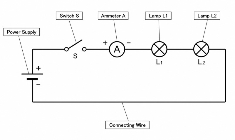
A wiring diagram emphasizes the actual positions of components and their wire connections, while a schematic emphasizes electrical logic. This distinction determines whether you need realistic connectors and wire routes, standardized abstract symbols, simulation, PCB integration, or flexible page-layout tools. It also explains why one program can be excellent for teaching circuit theory but awkward for automotive harnesses or home wiring plans.
This guide compares practical tool categories for instructional circuits, residential wiring, automotive systems, and industrial schematics. It also explains when to use IEC or ANSI symbols and gives a repeatable export and printing workflow. The named applications are established general-purpose, open-source, or web-based tools; for every product, pricing, plan limits, and quotas are subject to the official website.
1. What a Wiring Diagram Maker Must Represent
Begin by defining the deliverable in one sentence. For example: ‘A schematic showing how a sensor amplifier works,’ ‘A wiring diagram showing where three switches connect to two lamps,’ or ‘A harness diagram identifying connector pins and wire colors.’ These descriptions sound similar, but they require different visual structures. A logic-focused schematic may rearrange components freely for clarity, whereas a wiring diagram should preserve information about terminals, connectors, and physical routing.
For coursework and research, it is often useful to create two related figures instead of forcing everything into one page. Figure A can be a schematic that explains operation; Figure B can show the breadboard, connector, or installation wiring. Assign matching reference designators such as R1, C1, J1, and SW1 in both figures. This makes the work easier to reproduce and prevents readers from guessing whether two similarly drawn components are actually the same part.
Evaluate a wiring diagram maker with a small test before committing to a large project. Draw ten representative symbols, create one crossing and one connected junction, label five wires, add a multipin connector, and export the result. If symbols shift, text becomes too small, or junctions are ambiguous after export, the problem will become worse in a twenty-page document.
- Decide whether the primary goal is physical wiring, electrical logic, or both.
- List the required objects: symbols, terminals, connectors, wire numbers, cable names, and reference designators.
- Check whether the diagram must support simulation, PCB design, page references, or only static illustration.
- Test PDF or SVG export before drawing the full project.
- Keep editable source files together with the submitted or printed version.
2. Tools for Teaching Circuits and Student Coursework
For introductory electronics, Fritzing is useful when the learner must relate a physical breadboard to a schematic. Its breadboard-oriented presentation suits maker projects and classroom demonstrations in which component placement matters. A teacher can show the construction view next to the abstract circuit, while students can use consistent labels to connect the two representations. It is less appropriate when the main deliverable is a dense industrial control schematic with extensive terminal numbering and cross-references.
CircuitLab is a browser-based option for circuit drawing and analysis, with limited free usage; current pricing and quotas are subject to the official website. EasyEDA is also web-based and can support a progression from schematic capture toward electronic design work. KiCad is an open-source EDA suite combining schematic capture and PCB design, making it a strong choice for advanced coursework, laboratory projects, and research hardware that may eventually become a fabricated board. Its fuller engineering workflow can be more than is needed for a single classroom illustration.
For lecture slides, worksheets, or a simple conceptual circuit, draw.io/diagrams.net and LibreOffice Draw offer flexible general-purpose drawing environments. diagrams.net includes electrical symbol libraries, while LibreOffice Draw provides vector drawing and page-layout capabilities. These tools are convenient when annotation and visual composition matter more than electrical rule checking. However, users must manually maintain consistent symbols, junction dots, labels, and wire alignment because a general drawing application does not necessarily understand the circuit as an electrical network.
- Choose Fritzing when breadboard placement is central to the lesson.
- Choose KiCad when students need schematic capture plus a path to PCB design.
- Consider CircuitLab when browser access and circuit analysis are important; free usage is limited, and current terms are subject to the official website.
- Consider EasyEDA for a web-based EDA workflow; pricing, limits, and service details are subject to the official website.
- Use diagrams.net or LibreOffice Draw for static teaching figures, handouts, and heavily annotated slides.
3. Home Wiring Diagrams: Prioritize Layout and Safety
Residential diagrams often need to communicate where outlets, switches, luminaires, junction boxes, and distribution equipment are located. That makes them closer to wiring diagrams than pure schematics. A useful page may combine a simplified room or floor layout with lines representing cable runs. Each device should have an identifier, and repeated items should not be distinguished only by color because the document may be photocopied or printed in grayscale.
Among the listed tools, draw.io/diagrams.net and LibreOffice Draw are practical for floor-plan-like layouts because they allow flexible positioning, connectors, labels, and page composition. A user can build a small reusable symbol set for switches, receptacles, lights, and junction points, then lock the background plan to avoid moving it accidentally. QElectroTech may be more suitable when the project resembles a structured electrical installation or panel document rather than an informal room layout. QElectroTech is open source and intended for industrial electrical diagrams.
Separate the installation overview from circuit logic when the page becomes crowded. One sheet can show room positions and cable routes; another can show circuit relationships, protective devices, switching logic, and terminal connections. Add a legend containing symbol meanings, conductor-label conventions, and drawing status. A home wiring drawing is documentation, not authorization to perform electrical work: local electrical codes, permit requirements, conductor sizing, and safety procedures must be confirmed through applicable authorities and qualified professionals.
- Place a visible junction dot wherever conductors are electrically connected.
- Use bridge marks or clear gaps for wires that cross without connecting.
- Give switches, outlets, lights, panels, and junction boxes unique identifiers.
- Label both ends of important cables instead of relying on line color.
- Verify all code, permit, and installation requirements with official local guidance.
4. Automotive Wiring: Design for Fault Tracing
Automotive wiring diagrams are used not only to explain a system but also to locate faults. A technician may need to trace a path from a fuse through a relay, splice, connector, load, and ground point. Therefore, connector identifiers, pin numbers, splice identifiers, wire labels, and ground references are usually more valuable than decorative realism. Keep current flow or signal flow consistent across the page, and do not reverse the reading direction without a clear reason.
For a custom educational or research vehicle, diagrams.net or LibreOffice Draw can create a clear harness overview with manually defined connectors and wire routes. QElectroTech can be considered when terminal-oriented documentation and structured electrical pages are useful. KiCad is appropriate for the electronic circuitry and PCBs inside control modules, but a PCB schematic is not automatically a complete vehicle harness diagram. It may be clearer to maintain separate module schematics, connector pinout tables, and system-level wiring sheets.
Use a hierarchy rather than placing an entire vehicle on one enormous canvas. Start with a system overview covering power distribution and major modules, then create subsystem pages for lighting, sensing, communication, or actuators. On every detailed page, identify off-page destinations unambiguously—for example, by sheet number, zone, connector, and pin. If wire colors are included, add textual color codes and a legend so the diagram remains usable when printed without color.
- Identify connectors as J1, C101, or another documented scheme, and show every relevant pin number.
- Assign unique labels to splices and grounding points.
- Show fuses and relays in the traceable path rather than hiding them in notes.
- Use one overview page plus separate subsystem sheets for complex vehicles.
- Create a connector table listing pin, signal, destination, and relevant notes.
5. Industrial Schematics and Structured Documentation
Industrial electrical drawings commonly involve control circuits, terminal strips, motors, contactors, relays, sensors, programmable controllers, and power distribution. The key challenge is document structure rather than artistic drawing. Readers need stable device tags, terminal numbers, wire numbers, page references, and a predictable relationship between coils and contacts. The software should make repeated symbols and aligned connections efficient to manage across multiple sheets.
QElectroTech is an open-source application for industrial electrical diagrams and is the most directly specialized option in this list for that use case. KiCad is an open-source EDA tool for schematics and PCBs, so it is better aligned with electronic boards than with every aspect of plant or cabinet documentation. diagrams.net and LibreOffice Draw can produce visually correct industrial figures, but their general-purpose nature means that cross-references, tag consistency, and electrical semantics may require more manual checking.
Before drawing, establish a project convention sheet. Define device prefixes, terminal notation, wire-number rules, page numbering, title-block fields, revision notation, and the selected symbol standard. For a thesis or teaching example, include enough of this convention to let another reader interpret the page without proprietary background knowledge. For actual industrial deliverables, customer, employer, and regulatory requirements take priority, and exact requirements are subject to the applicable official guides.
- Create the title block and page-numbering system before adding circuits.
- Number wires or networks consistently across sheet boundaries.
- Show terminal strip identifiers and terminal numbers explicitly.
- Provide cross-references between relay coils and associated contacts when needed.
- Run a final manual audit for duplicate device tags, missing destinations, and unexplained abbreviations.
6. Choosing Between IEC 60617 and ANSI/IEEE Std 315
Circuit symbols have two major systems: IEC 60617, commonly used internationally and in Europe, and ANSI/IEEE Std 315, commonly used in North America. The same component may have different symbols in the two systems. A resistor, for example, is represented as a rectangle in IEC and as a zigzag line in ANSI. Neither visual form should be treated as universally correct without considering the audience and required standard.
Choose the system according to the destination of the document rather than personal preference. For a class assignment, follow the instructor’s convention. For a thesis, use the convention accepted by the department and apply it consistently; exact institutional requirements are subject to the official guide. For a journal or conference paper, inspect its author instructions and recent publications, but do not infer mandatory rules unless they are explicitly stated. For professional work, follow the client, organization, and jurisdiction requirements.
Avoid mixing IEC and ANSI variants merely because they are the first results in a symbol search. If a mixed convention is unavoidable—for example, when reproducing a manufacturer-specific connector or block—explain it in the legend. Build or select one controlled symbol library at the beginning of the project. Check at least resistors, capacitors, inductors, switches, grounds, batteries, diodes, transistors, and connector symbols before approving the library.
- Use IEC 60617 when the project or audience specifies the international or European convention.
- Use ANSI/IEEE Std 315 when the project or audience specifies the North American convention.
- Do not change symbol systems between pages in the same document.
- State the chosen convention in a legend, caption, methods section, or drawing note.
- Treat manufacturer drawings as references, not as proof that one symbol convention applies to the entire project.
7. Exporting and Printing from a Wiring Diagram Maker
A technically correct diagram can still fail if thin lines disappear, labels become unreadable, or symbols move during export. Prefer vector output such as PDF or SVG for papers, handouts, and scalable illustrations. Vector lines remain sharp when enlarged and generally produce smaller, cleaner technical figures than screenshots. If a publisher, learning platform, or submission system requires a raster format, follow its official guide; do not guess the required format, dimensions, or resolution.
Draw at the intended final aspect ratio and test readability at the actual output size. As a practical starting point, keep ordinary figure text around 8–10 pt at final printed size, then adjust for the destination and verify against the official guide. Use consistent line-weight classes: one for ordinary conductors, a heavier one for major buses or boundaries, and a lighter one for construction guides if those guides remain visible. Avoid hairline strokes because printer and PDF behavior can vary.
Run a five-part preflight before submission: export to the target format, reopen the exported file in a different viewer, inspect it at normal reading size, print one page at 100 percent scale, and test a grayscale version. Confirm that junction dots, subscripts, polarity marks, terminal numbers, and dashed lines survive. Fonts should be embedded or converted according to the destination’s official requirements, and special characters should not be replaced during export.
Maintain both a master file and delivery files. A useful naming pattern is project_system_sheet_revision, followed by the extension, such as labpower_control_02_R3.pdf. Store the symbol library or custom symbols with the source document when possible. Before editing a published or submitted figure, increment the revision instead of overwriting the only approved copy.
- Prefer PDF or SVG for sharp, scalable line art.
- Use raster files only when required, with resolution and format set according to the official guide.
- Print one proof at 100 percent scale and inspect it from a normal reading distance.
- Check that color-coded wires remain distinguishable in grayscale.
- Remove hidden objects, unused symbols, comments, or private notes before distribution.
- Archive the editable source, exported figure, legend, and revision record together.
FAQ about this diagram
What is the best free wiring diagram maker for students?
The answer depends on the assignment. KiCad is an open-source option for formal schematics and PCB-related projects, while diagrams.net and LibreOffice Draw work well for static figures and annotations. QElectroTech suits industrial electrical drawings; all current product terms and download conditions are subject to the official website.
Should I use IEC or ANSI symbols in my circuit diagram?
Use IEC 60617 for an international or European convention and ANSI/IEEE Std 315 for a North American convention when that choice matches the audience or requirement. Do not mix systems casually: even a resistor changes from a rectangle in IEC to a zigzag line in ANSI. For assignments, theses, and publications, follow the relevant official guide.
Can I make a home wiring diagram in draw.io or diagrams.net?
Yes, diagrams.net can be used for a room layout, device positions, cable routes, labels, and electrical symbols. Create a legend, mark connected junctions clearly, and label both ends of important runs. The resulting drawing does not replace local electrical codes, permits, or review by a qualified professional.
How do I export a wiring diagram for my thesis without blurry lines?
Export to a vector format such as PDF or SVG when your institution accepts it, rather than taking a screenshot. Reopen the exported file, inspect it at final size, and print a 100 percent proof to check text and junction dots. File format, font, size, and resolution requirements must follow your institution’s official guide.