Network Topology Diagram Generator
Free online Network Topology Diagram generator: get a fully labeled figure in about 90 seconds. The AI plans the must-have label list first, then renders a clean textbook-style diagram — every label editable afterwards, ready for papers, assignments and slides.
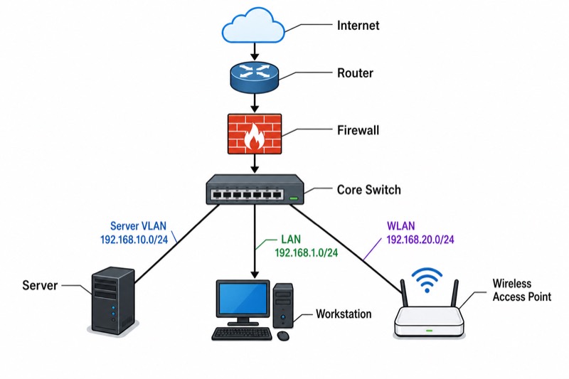
Labels included in this diagram
- Internet
- Router
- Firewall
- Core Switch
- Server
- Workstation
- Wireless Access Point
- LAN 192.168.1.0/24
- Server VLAN 192.168.10.0/24
- WLAN 192.168.20.0/24
✓ Accurate labels ✓ Edit text after generation ✓ PNG for papers, posters & slides
 OUTPUT · 16:9 · PNG
What this diagram shows
This network topology diagram represents a star-based enterprise network. A router provides connectivity between the local network and an external or upstream network, while a firewall enforces security policy between trust zones. The central switch forms the access-layer connection point for wired devices, including servers and workstations. A wireless access point extends network access to mobile clients through radio communication, although the access point itself is connected to the wired switch. Standard device icons and labeled links show the physical or logical arrangement. Subnet labels identify IP network boundaries, helping students distinguish topology from addressing and understand how devices participate in communication.
The communication logic follows a layered path rather than simply the visual direction of the lines. A workstation sends an Ethernet frame to the switch, which forwards it according to its MAC address table. If the destination is outside the local subnet, the default gateway, normally provided by the router, is used. Traffic crossing a security boundary is inspected by the firewall according to configured rules. Server traffic may remain inside the local LAN or cross a routed boundary, depending on subnet design. Wireless clients first communicate with the access point, which bridges or segments their traffic toward the switch.
What a correct diagram must include
- Topology type: Label the arrangement as a star topology so the central dependency and spoke connections are unambiguous.
- Core devices: Include the router, firewall, and switch because they represent routing, security enforcement, and local Layer 2 forwarding functions.
- Endpoint devices: Show at least one server and several workstations to distinguish service providers from user hosts.
- Wireless access: Draw the wireless access point with a wired uplink to the switch and indicate wireless client connections separately from cable links.
- Network links: Use clear lines with consistent conventions, and distinguish physical connections from logical or wireless associations when necessary.
- Subnet labels: Mark each IP subnet or VLAN near the relevant interfaces so the diagram communicates addressing boundaries, not only device placement.
- Traffic direction: Add arrows only when explaining a particular packet flow; otherwise avoid implying that ordinary network links are one-way.
- Legend and scope: Provide a small legend for icons, line styles, and trust zones so readers can interpret the diagram consistently.
Common mistakes
- Drawing every device directly to the router and calling it a star LAN, which confuses the access switch with the network gateway.
- Placing the firewall after the switch without explaining the security boundary, making the intended trust-zone relationship unclear.
- Connecting the wireless access point only by radio lines, even though its backhaul connection to the wired switch is essential.
- Using subnet labels as if they were device names, or placing devices from different IP subnets on one unlabeled segment.
- Treating the diagram as a packet-flow chart by adding permanent arrows to bidirectional links without specifying the protocol or traffic scenario.
Teaching tips
Use the diagram during an introductory lecture, design exercise, or exam review. Ask students to trace a packet from a workstation to a local server, then to a remote network, identifying the switch, default gateway, firewall policy, and relevant subnet at each step. Follow with questions such as: Which device makes a forwarding decision from a MAC address? Which device routes between IP networks? Where is the security boundary? Students can then redraw the topology with VLANs or failure points, linking the visual model to OSI layers, IPv4 addressing, routing tables, and network availability analysis.
FAQ about this diagram
Why is the switch placed at the center of a star topology?
The switch is the central Layer 2 forwarding point for connected hosts. Each endpoint has a separate link to the switch, so a single access-link failure usually affects one device rather than the entire LAN.
What is the difference between a router and a firewall in this diagram?
A router forwards packets between different IP networks according to routing information. A firewall controls permitted traffic across a security boundary using policy rules; one device may perform both functions, but their logical roles remain different.
Does a subnet label describe a physical cable or a logical network?
A subnet is primarily a logical IP addressing boundary, not a cable type. One physical switch can carry multiple subnets through VLANs, while a single subnet may also span multiple physical links when the design permits it.